Trankley Mahler
Detailed Hover DR1 Documentation
About
This documentation contains the contents of the final-deliverable my team presented for our Capstone Design project. We placed 1st place in the ECE department competeing against fellow CE/EE majors at the University of Texas at Dallas.
Reactive Audio Hoverboard
UTDesign Fall 2023
UTDesign Team 1792
- Trankley Mahler
- Jimmy Tran
- Jonathan Abshiro
- Kevin Mikhaiel
- Tate Froh
- William Lim
Faculty Advisor:
Dr. Leo Estevez
Instructor:
Dr. Marco Tacca
Abstract
The team designed and built a market-ready kit, marketed as the HoverDR1 Learning Module, that allows consumers to convert their hoverboard devices into learning platforms using off the shelf parts and a provided instruction guide. The kit is powered by an Arduino Uno, and controls the movement of the hoverboard based on the audio frequencies detected by the module. The kit includes the aforementioned Arduino Uno, as well as a microphone module, a motor, a casing, a mounting solution, an emergency stop mechanism, and a motor relay. This device allows parents to teach their kids the basics of engineering, STEM, and software development using a guided, but expandable, learning platform.
TABLE OF CONTENTS
- Introduction
- Review of Conceptual and Preliminary Design
- Problem Analysis
- Summary of Specifications
- Main Features of Design Problem
- Technical Approach
- Decision Analysis
- Solution Alternatives
- Effectiveness Criteria
- Decision Analysis
- Basic Solution Description
- Subsystem 1 (Motor Controls)
- Subsystem 2 (FFT)
- Subsystem 3 (Chassis)
- Performance Optimization and Design of System Components
- Design Criteria
- Subsystem 1 (Motor Controls)
- Subsystem 2 (FFT)
- Subsystem 3 (Chassis)
- Components
- Subsystem 1 (H-Bridge and 30RPM Motor)
- Subsystem 2 (KY-038 arduinoFFT functions)
- Subsystem 3 (Material Choices)
- Fabrication/Assembly Process
- Subsystem 1
- Subsystem 2
- Subsystem 3
- Performance Evaluation
- Metric 1: Frequency identification and adjustment
- Metric 2: Universality
- Testing Procedure
- Metric 1
- Metric 2
- Project Implementation/Operation and Assessment
- Overview of Final Implementation
- Operational Test Results
- Evaluation of Results Relative to Design Criteria
- Kickstarter
- Conclusion, Overview of Work Statement
- Future Work Recommendations
- Other Issues
- Ethics
- Issue 1(Safety Stop Feature)
- Issue 2(Operational Manual)
- Issue 3(Warnings in Quickstart Guide)
- Issue 4(Backer Confidentiality)
- Operating Instructions
- Setup
- Mode 1 operation
- Mode 2 operation
- Cost Estimate
- Materials and Construction
- Estimate of Design Cost
- Project Management Summary
- Tasks Completed
- Tasks Pending Completion
- Time Allocated
- Facilities Used
- Personnel
- Appendices
- Bibliography
- Quickstart Guide
- Design Schedule
- Construction Schedule
- Equipment List and Cost Breakdown
- Subsystem 1
- Subsystem 2
- Subsystem 3
- Design Drawings
- Phase 1
- Phase 2
- Phase 3
- Other Part Designs
- Code
Acknowledgements
We would like to thank the following people for their guidance and help with the project:
- Professor Leo Estevez
- Professor Marco Tacca
1. Introduction
The RAH team at UTD has developed the HoverDR1 attachment designed to allow control of a hoverboard through the use of auditory stimuli. The purpose of the document is to provide the methodology for verifying the requirements (as stated in the Functional Specification) have been satisfied by the current design.
The attachment is mounted on top of the hoverboard and controls it by mimicking the way it would be controlled normally. The system consists of a chassis and a shaft that runs across the hoverboard, both the chassis and shaft are strapped down to the left and right plates on the hoverboard to mimic someone stepping on it. The chassis holds all of the components of the design, the arduino, motor, motor controller, and microphone. The system is powered by one external battery that is also weight-biasing the hoverboard forward. When the system is on, if the microphone detects one of two predetermined frequencies, the arduino will send a signal to the motor controller, which will rotate the motor’s shaft left or right according to the frequency detected. The motor movement will rotate the hoverboard axis and cause it to turn.
We have designed the arduino code to interface the microphone and motor controller, we have also designed the mechanical function and chassis of the attachment. The off-shelf components are the arduino, battery, microphone, motor, motor controller, and various fixtures(screws, washers, etc).
2. Review of Conceptual and Preliminary Design
- Problem Analysis
- Summary of Specifications: The attachment will lay on top of the hoverboard and be completely independent of the hoverboard. Meaning that the attachment will be able to be compatible with various hoverboards. The attachment should be able to obtain frequencies and utilize them as commands to control the hoverboard that it is on. These commands consist of, turning left, right, forward, and stopping.
- Main Features of Design Problem
- Device Development
- An electromechanical attachment to a Hoverboard which leverages the Bluetooth Audio integrated in the Hoverboard to control its movements.
- The component cost of this attachment should be less than $50. (A hoverboard will be provided to the team for development and testing.)
- An existing downloadable audio app should be used to control the Hoverboard.
- The Hoverboard DR1 attachment may be prototyped with an off the shelf EVM which enables audio sensing and motor control.
- Hover DR1 Crowdfunding
- 1st Month: Order Relevant EVMs and Prototype an Audio Controller
- 2nd Month: Test to have first Proof of Concept and Stage for Campaign(file Provisional Patent)
- 3rd Month: Launch Campaign and Report on progress towards making lower cost integrated solutions available to the public with daily posts to the campaign.
- 4th Month: Continued posts on progress towards working boards and posts on how multiple units are being produced and tested.
- 5th Month: Shipping Units to Backers
- 6th Month: Preparation/Presentation of Project Results at UTD
- Technical Approach Due to the nature of our unique project, we were split into two main teams to execute effectively. These teams were Development and Marketing, while we all helped on both parts of this project, we had people focus mainly on one or the other.
- Deveopment:
- Marketing
- Decision Analysis
- Solution Alternatives
- A device that functions similarly to the Hover DR1 could be created using a remote control car. However, the decision to use a hoverboard was based on the concept that many people have hoverboards laying around their house that they do not use anymore, and that hoverboards have a “cool” factor that gets people interested.
- Again, a device that could compare to the Hover DR1 could be created using remote controls based on radio frequencies, rather than audible sound, however, the decision to make it operate solely on sound would add uniqueness and the ability for the hoverboard to dance to music in theory.
- Designing and using a custom PCB to contain our device on one board was considered. This would allow the Hover DR1 to have a significantly smaller form and be simpler to install. The decision to use premade devices, such as the arduino and motor controller was made based on the modular nature of the device. We wanted the device to be approachable by anyone who wanted to add their own modules or functions to it, this adds to the educational aspect of the project.
- Another device that was considered to be used as our main board is a Teensy USB development board. This is much smaller than the Arduino Uno but lacks the same modularity and accessibility that our educational platform demands.
- Effectiveness Criteria Our decisions were made by rating the alternate solutions that we came up with based on the following criteria;
- Initial Viability
- Cost
- Modularity
- Size
- Accessibility
- Decision Analysis The Arduino Uno platform scored the highest based on our trade studies. We made the decision to use the Arduino platform mainly because of its accessibility and cost-effectiveness. Modularity became more of a concern as our project progressed, therefore we decided to stick with the arduino platform for adding things like radar or other functions to the device.
The development team consisted of Trankley, Tate, William, and Jimmy. This group was in charge of the physical development of the prototypes and the coding of the device itself. This team would meet to experiment with new hardware ideas that would improve the overall performance of the device while minimizing the cost to keep it under that $50 price point.
The marketing team consisted of Jonathan and Kevin. This group would meet with Leo and discuss the strategy for the Kickstarter. They also would go to engineering conventions such as Texas BEST, to show them the device and get feedback from middle school and high school students.
Even though we were split into these groups, it is important to note that all group members contributed significantly to both sides of the project.
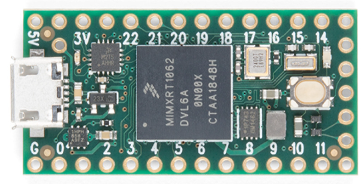
Figure 1: Teensy 4.0
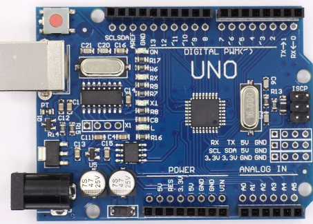
Figure 2: Arduino R3 Platform
Microcontroller Platform Trade Study
Table 1: Arduino R3 Platform
| Criteria | Max Score | Score | Weight | Weighted Score | |
|---|---|---|---|---|---|
| 1 | Initial Viability | 5 | 5 | 25% | 25% |
| 2 | Cost | 5 | 5 | 15% | 15% |
| 3 | Modularity | 5 | 5 | 25% | 25% |
| 4 | Size | 5 | 3 | 15% | 9% |
| 5 | Accessibility | 5 | 5 | 20% | 20% |
| Total | 100% | 94% |
Table 2: Custom PCB Platform
| Criteria | Max Score | Score | Weight | Weighted Score | |
|---|---|---|---|---|---|
| 1 | Initial Viability | 5 | 3 | 25% | 15% |
| 2 | Cost | 5 | 2 | 15% | 6% |
| 3 | Modularity | 5 | 1 | 25% | 5% |
| 4 | Size | 5 | 5 | 15% | 15% |
| 5 | Accessibility | 5 | 2 | 20% | 8% |
| Total | 100% | 49% |
Table 3: Teensy 4.0 Platform
| Criteria | Max Score | Score | Weight | Weighted Score | |
|---|---|---|---|---|---|
| 1 | Initial Viability | 5 | 5 | 25% | 25% |
| 2 | Cost | 5 | 5 | 15% | 15% |
| 3 | Modularity | 5 | 3 | 25% | 15% |
| 4 | Size | 5 | 5 | 15%</ | 15% |
| 5 | Accessibility | 5 | 2 | 20% | 8% |
| Total | 100%</ | 78% |
The custom PCB idea would have been an expensive solution, however, it would have likely been the most space-efficient one. The DR1 device could have been much smaller using a custom board, however, it would lose its modularity entirely. This is something that would have been more viable if we were creating a product that was intended to not be opened up and experimented with.
The Teensy platform was one that was considered as well. Its size was smaller than the arduino, which was enticing, and its cost was comparable to the arduino platform, making it a very good option at first glance. However, it was lacking in the educational requirements of our project, like modularity and accessibility. While it likely could have been made modular, the simplicity of the Arduino is what kept us with it instead of the Teensy.
3. Basic Solution Description
The Hover DR1 consists of the following components; an Arduino Uno R3 controller, a DC geared motor, a microphone, chassis, an L298N motor controller, and a 12V portable battery. The audio comes from the hoverboard’s on-board Bluetooth speaker. The analog signal that is detected by the microphone is sent to the arduino. Our arduino uses the fast-fourier transform function in the arduino fft library to determine the dominant frequency that is being detected. Based on the dominant frequency that is detected, the arduino sends a signal to the motor controller to turn the motor either clockwise or counter-clockwise. The motor controller sends the correct voltage to the motor and the action is carried out. The rotation of the motor is translated through the main shaft across the hoverboard’s pressure plates, twisting the hoverboard and mimicking the movement of someone standing on it trying to turn. The hoverboard is weighted forward so that it is constantly moving in a direction.
We have implemented a safety-stop feature so that the hoverboard will deactivate after 10 seconds of inactivity or the stop frequency is detected by the microphone. The safety-stop functions with a linear actuator powered by the arduino which simply pushes the power button on the hoverboard when the stop-procedure is initiated.
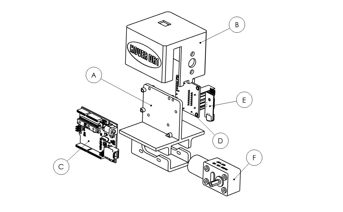
Figure 3: Depiction of the Components of the main system
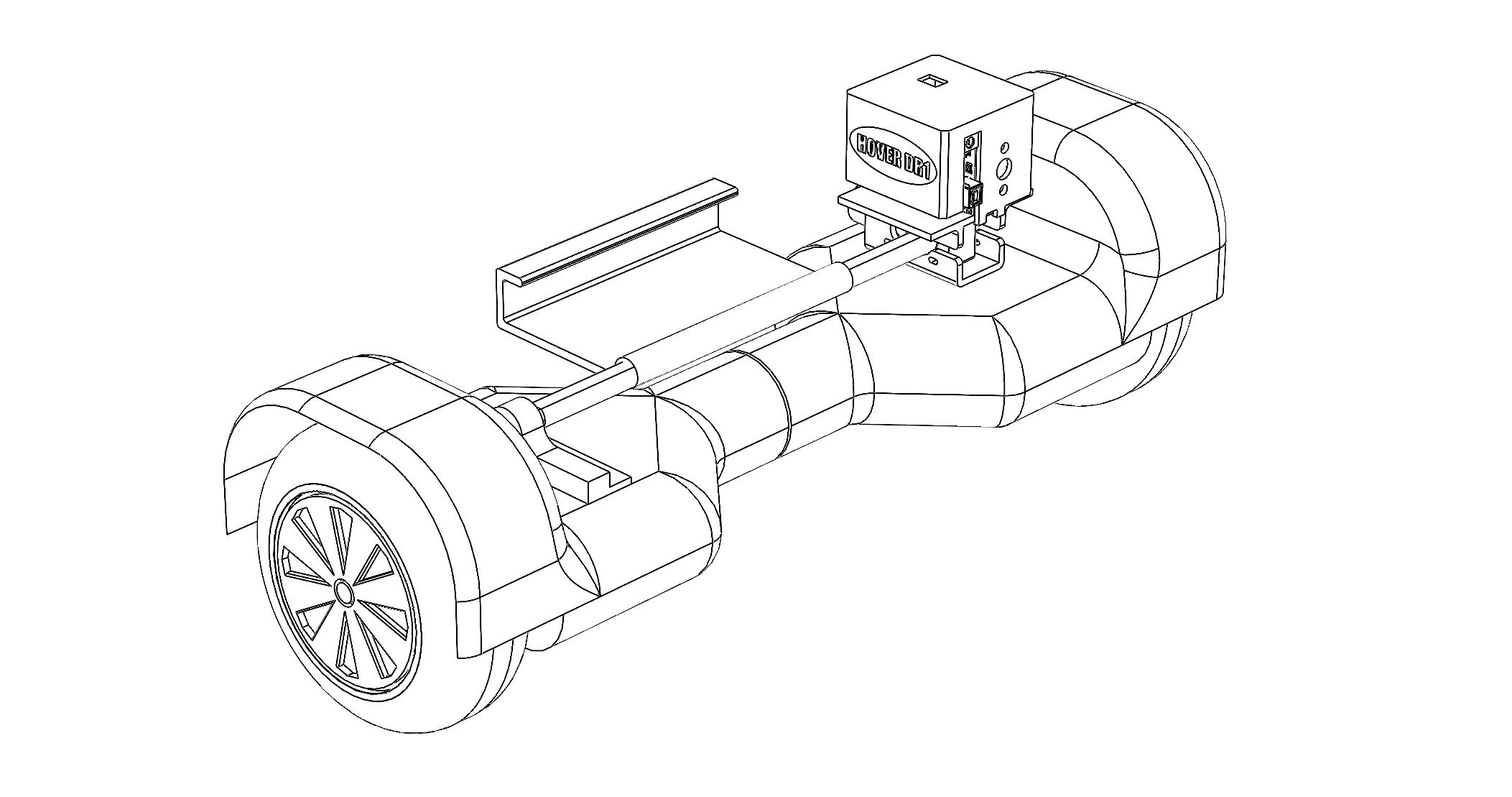
Figure 4: Depiction of the device on the hoverboard with the main shaft and biasing mount
- Motor Control
- Audio Processing
- Chassis A chassis is needed to hold all of the components that are to be used in the Hover DR1 device. The chassis needed to be rigid enough to hold the components so that they are fastened securely and in a compact manner, for this reason, and the expected custom nature of the project, we decided to 3D print all parts of the chassis out of PLA filament. The only part that was not 3D printed was the main shaft due to the rotational forces on it. The entire chassis consists of; a main chassis, chassis cover, rotating arm, forward-biasing mount, and safety-stop holder.
A motor driver plays an important role in controlling both the speed and spinning direction of a DC motor. Its significance becomes particularly pronounced when integrated with technologies such as audio processing. In this context, the motor driver, equipped with an audio processing code, is designed to modulate the speed and direction of the DC motor. The real-time adjustments are possible through the use of Fast Fourier Transform (FFT) code, allowing the motor driver to respond to audio signals. The mechanical attachment is designed to activate the hoverboard pressure plates, establishing a connection between the motor driver and the physical movement of the hoverboard. As a result, the motor driver, in tandem with its mechanical attachment, exerts influence on the hoverboard's motion, facilitating turns and stops.
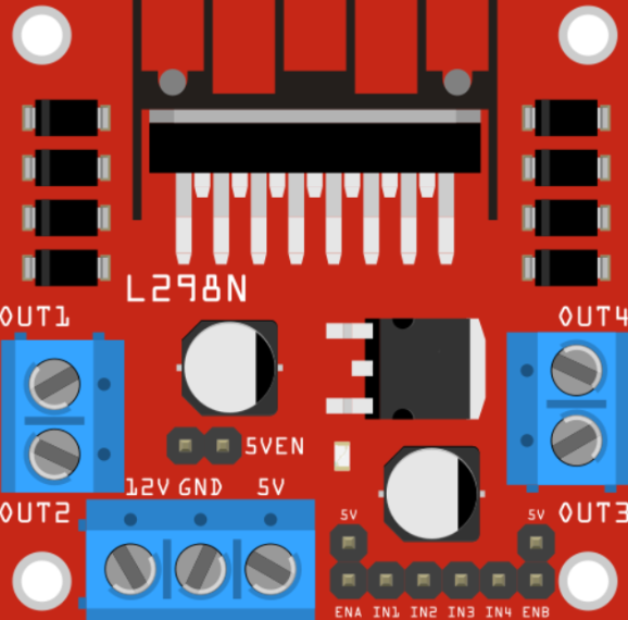
Figure 5: L298N Motor Controller layout
The microphone picks up the sound emitted from Bluetooth speakers from the hoverboard. From here the audio is sent to the Arduino. Once the sounds are received by the Arduino, an FFT operation is performed on the sound signal. The signal is broken up into different frequency components. The largest frequency component, which is the dominant frequency, is used to compare different set frequencies on the Arduino code. If the dominant frequency matches a set frequency a command is sent to the motor controller. Some of the commands consist of turning left, right, and a stop/ turn off hoverboard command. In addition, the commands are set up in a finite state machine to prevent commands from repeating multiple times when a command is received. For example, In order to vary the turning speed there are two different angles at which the device can turn the hoverboard. Each of these angles is one state in the finite state machines. Turning the opposite direction moves the states in the opposite direction. Finally, there is a heartbeat command that automatically turns off the hoverboard if no commands are sent in a predetermined time frame.
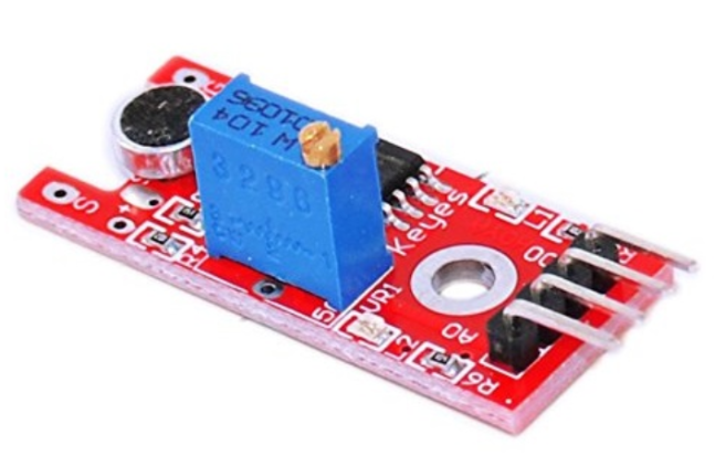
Figure 6: KY-038 Microphone for audio proccesing
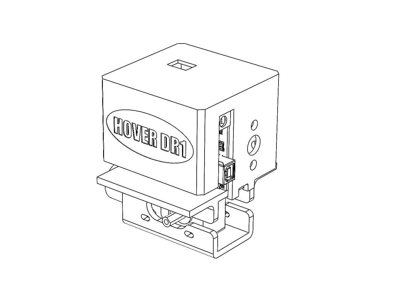
Figure 7: Main Chassis with chassis cover
The main chassis is where the arduino, microphone, motor-controller, and motor are mounted, this is the central part of the device. The chassis cover is an enclosure that clips onto the main chassis and covers the components while leaving open ports for the necessary connections. The rotating arm is mounted to the main shaft and branches off from the main shaft in a “T” shape. This is so when the shaft rotates, the arm will apply force off-axis from the hoverboard’s main rotating axis. The forward-biasing mount is around the main shaft and can rotate freely around it, but rests on the front of the hoverboard. The purpose of the forward-biasing mount is to hold the battery for the device as well as provide a weight on the front of the hoverboard which causes it to move forward indefinitely.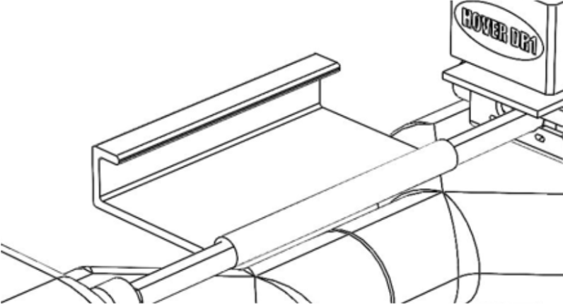
Figure 8: Battery holder and forward bias
The safety-stop holder is a 3D-printed mount for the linear actuator that makes up the safety mechanism. The holder is mounted with straps to the hoverboard and can be aligned with the power button on most hoverboards so that, when activated and calibrated correctly, the power button can be pushed remotely and the hoverboard will turn off.Performance Optimization and Design of System Components
- Design Criteria
- Motor Control
- Audio Processing
- Chassis
- Components
- Motor Control
- L298N DC Motor Driver
- Arduino
- Battery/Power supply
- DC Motor
- Wires
- Audio Processing
- KY-038
- Arduino R3
- Arduino FFT Library
- Chassis
- PLA Construction
- 13 x 4-40 x 1/4' screws
- 9 x 4-40 bolts
- Creality CR-10 Printer
- 300 x 8mm steel rod
- straps
- Fabrication/Assembly Process
- Motor Control
- Audio Processing
- Chassis
- Performance Evaluation
- Metric 1: Frequency identification and adjustment
- Metric 2: Universality
- Size
- Weight Limit
- Built-in Speaker Presence
- Power Button Location
Performance optimization of motor control depends on the specifications. For the L298N motor driver, its input voltage ranges from 5V to 12V and the output channels will allow 5V to 12V DC motors to be attached. Performance optimization will not be vital concerning the motor control and DC motor because little force is required to activate pressure plates. Through testing at least a 30 RPM motor is sufficient. To maximize speed the motor power supply should have +2V more than the voltage required on the motor, although not needed. The performance optimization between the motor control and battery is the use of a 12V battery. Combining these three components along with an Arduino will allow the motor controller to control the DC motor effectively.
The microphone(ky-038) will be attached to the chassis of the attachment and will pick up sounds coming from the hoverboard’s speaker. The audio signal is then sent and processed by an Arduino R3. An FFT operation is performed on the audio signal by the Arduino R3 and then the dominant frequency is used as the command to be sent to the motor controller. To ensure that the audio processing is efficient, the sampling speed is fine-tuned to remain accurate but remain at sampling speeds that do slow the real-time operation. In addition, only the dominant frequency is used for commands to reduce the complexity of the FFT operation. To reduce redundant commands, like a left turn command when the hoverboard is already moving left, a state machine will be used. The state machine allows the Arduino to remember a few previous commands and prevents the redundant commands from being executed. The microphone placement is also important to ensure that the hoverboard’s speaker is properly picked up. So in order to ensure a solid performance from the microphone, the microphone is placed relatively close to the speaker but not too far from the Arduino.
The chassis needed to be universal for all hoverboards. Therefore the design was required to not be specific to the hoverboard we were testing on. Ideally, it would be adjustable to fit other sizes and shapes of hoverboards. We decided to go with a design that was universal in that it fit most hoverboards on the market and it would be rare to find one that it wouldn't work on. The rotational shaft length is the main concern when considering the fit of the device. We made the shaft length fit the medium sized hoverboard we were testing on, that way a smaller or larger board would likely still fit. Following the same requirement of universal mounting, the device is mounted with straps, this allows for any size hoverboard to be compatible, as the straps are widely adjustable. The chassis takes the strap mounting system into account by incorporating geometry that compliments the mounting mechanism. This includes, “wings” that extrude out from the chassis to hold the straps as they are tightened down onto the hoverboard.
The chassis needed to be rigid enough to not break under the forces of the straps, as they needed to be tight enough to activate the pressure plates of the hoverboard. Therefore, the PLA construction of the chassis is made thick enough to withstand those forces. The part of the chassis that holds the motor also needed special consideration, as the motor has a significant amount of torque.
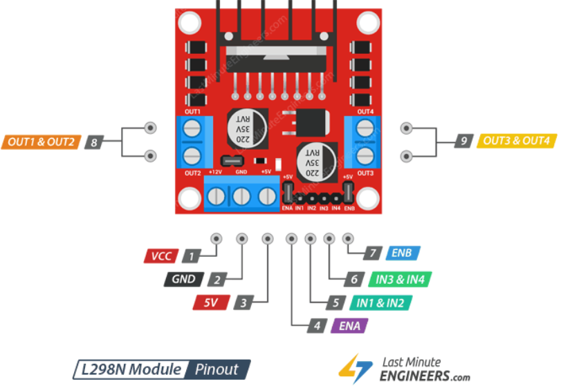
Figure 9: L298N Motor Contoller
Components for motor control
Figure 10: KY-038 Microphone
Audio processing components
Chassis components:
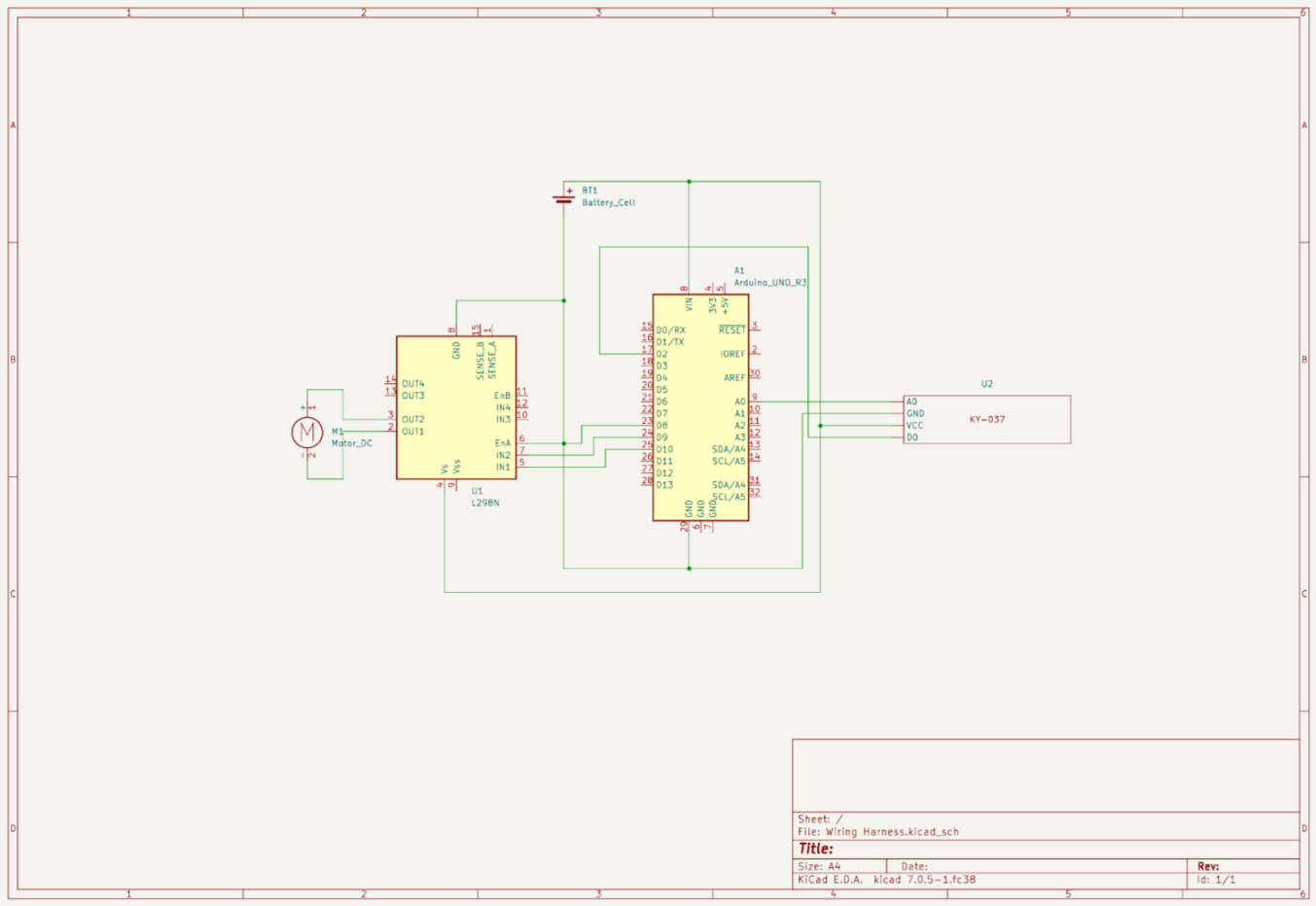
The motor controller is attached to the chassis along with the DC motor. The motor controller has pins that connect the majority of the hardware. Firstly we have the VS and GND pins that connect to the power and ground of the battery respectively. The motor control has OUT1-OUT4 pins that connect to the DC motors. We used OUT1 and OUT2 to connect it. Lastly, we have pins ENA, ENB, IN1 & IN2, these three pins will be attached to the arduino. We will use all these pins to control the geared motor. ENA and ENB are used to turn on and off the motors. IN1 & IN2 are used to control the spinning direction of the motor. All of these components will be attached to the chassis and enclosed.
Both the microphone and the Arduino will be attached to the chassis of the attachment. In addition, the microphone will be positioned to be relatively close to the speaker to ensure the microphone can reliably listen to the speaker on the hoverboard. Due to the educational background of the device, most parts will be breakout boards rather than a dedicated custom PCB. This allows for the modularity of the device and the ability to scale and add more sensors to the device. Due to the microphone being a breakout board, jumper wires are also used to connect to the Arduino instead of soldering wires.
The chassis was fabricated using 3D printing with PLA filament. First, the arduino, motor, motor controller, and microphone should be screwed into the chassis using the screws and bolts. Once these components are mounted, the forward-bias mount can be slid onto the main shaft and connected to the motor output shaft. This is the main construction of the device. Then the components can be wired together according to the wiring diagram in the quickstart guide. The main assembly can be strapped down to the hoverboard to activate the pressure plates. Then the safety stop mechanism can be mounted with the straps and aligned to the power button, then wired to the arduino on the main assembly.
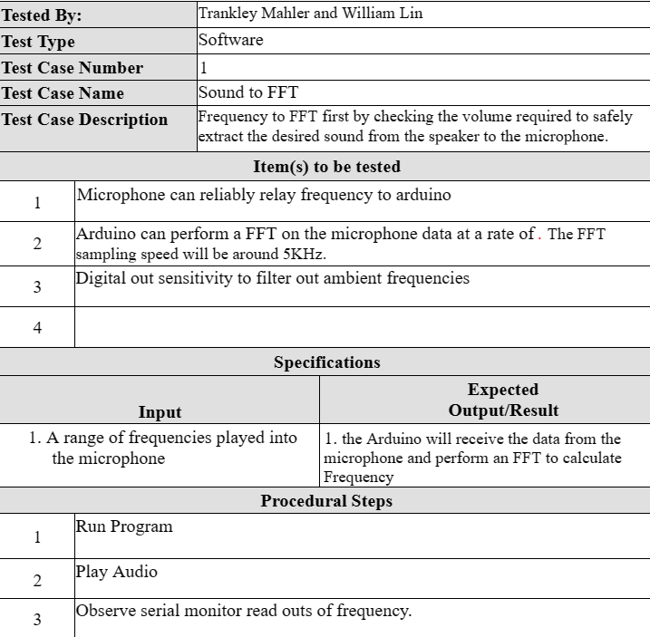
The HoverDR1 module is designed to detect various frequency ranges and subsequently modulate the motor's power output in response to the identified frequency. During our testing phase, the microphone consistently demonstrated its ability to accurately identify and maintain the detected frequencies, even when the hoverboard was in motion. This functionality showcases the module's reliability and effectiveness in real-world scenarios.
The HoverDR1 module is specifically engineered for universal compatibility, enabling it to seamlessly integrate with any pre-existing hoverboard model. In our evaluation, we meticulously affixed and tested the module on a diverse range of hoverboards, encompassing varying sizes, weight limits, built-in speaker configurations, and power button locations. Impressively, the HoverDR1 module proved to be adaptable and successfully accommodated all three hoverboard models we assessed, irrespective of their differences in:
5. Testing Procedure
- Test Case #1: Sound to FFT
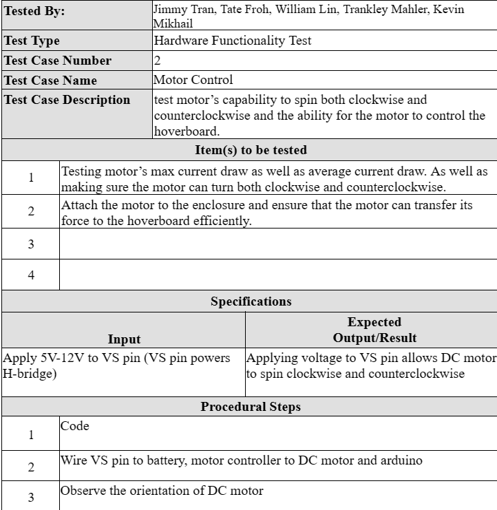
- Test Case #2: Motor Control
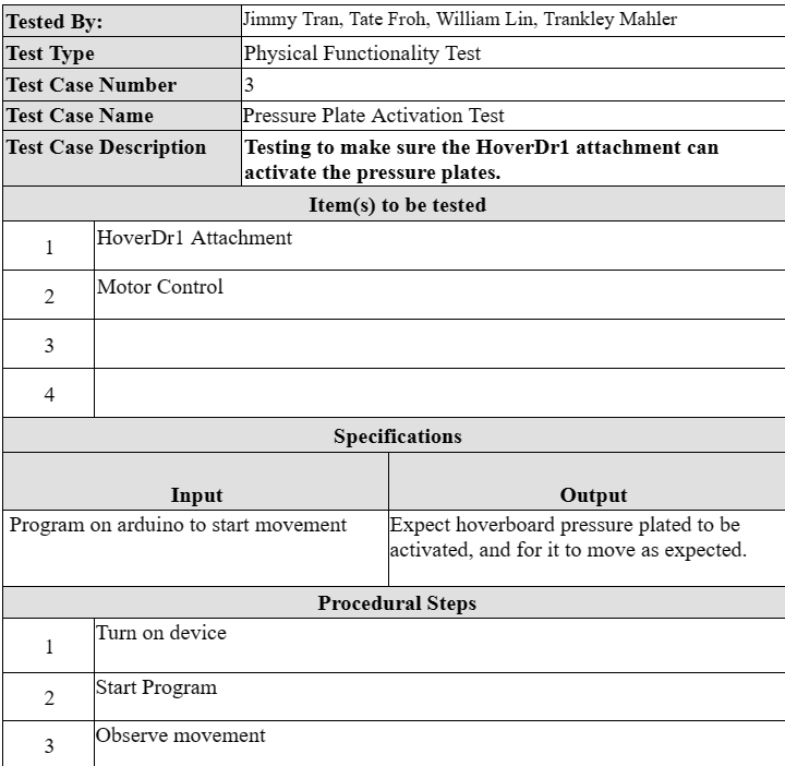
- Test Case #3: Pressure Plate Activation
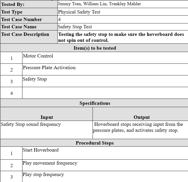
- Test Case #4: Safety Stop
6. Project Implementation/Operation and Assessment
- Overview of the final implementation
- Operational Test Results
- Evaluation of Results Relative to Design Criteria
- Kickstarter
The final implementation of the hoverboard project introduces the ability to control the movement of the hoverboard using sound. This innovative technology is not only a leap forward in user interaction but also serves as a unique learning platform for aspiring young engineers.
The sound-controlled navigation system leverages advanced audio processing algorithms and onboard microphones to interpret specific commands and translate them into precise movements. Users can effortlessly maneuver the hoverboard by emitting distinct sounds or modulating their voice pitch. This feature adds an element of fun and engagement to the user experience.
Beyond its immediate benefits, the sound-controlled feature serves as an educational tool, particularly for young engineers entering the field. The underlying principles involve signal processing, machine learning, and sensor integration, providing a practical and tangible application for theoretical knowledge. The modular nature of the hoverboard attachment encourages experimentation and tinkering, allowing young engineers to explore the intricacies of sound-based control systems and expand their understanding of real-world applications.
The learning platform aspect is further enhanced by open-source software and documentation provided by the hoverboard project team. This empowers young engineers to delve into the code, modify algorithms, and experiment with different configurations. The hoverboard attachment becomes a canvas for creativity, encouraging the next generation of engineers to think innovatively and contribute to the evolution of personal transportation technology.
In essence, the sound-controlled movement feature not only elevates the hoverboard's user experience but also serves as a gateway for learning and exploration, nurturing the curiosity and passion of young engineers. The hoverboard project, with its forward-thinking technology and educational potential, paves the way for an exciting future where innovation and learning go hand in hand.
The Hoverboard attachment was tested on multiple models and fits properly. The microphone, after calibration, properly identified the target frequencies with a +-2% accuracy.
Our device successfully fulfilled the requirements of the hardware design criteria. Our microphone was able to detect the frequency, which we then processed using an FFT library on the arduino. This was used to determine what command to run based on which frequency range we were in. Our kickstarter didn’t reach the goal of $8,000, but we did learn valuable lessons on how to format and manage a crowdfunding campaign.
Planning for the Kickstarter Campaign of the HoverDr1 project started in July. The first step to determining how to market the project was to determine where it would hold value. We were supplied with a group of students from a Human-Computer Interactions class on the home campus, UTD. From July to Early August we collaborated on deciding on an ideal market, creating social media, landing pages, and surveys.
When choosing our target audience we wanted to select a group that would be more likely to have access to hoverboards as well as potentially be interested in engineering. Therefore we decided to aim our product primarily at prospective engineering students. By deciding this early in the process of building our design we were able to make choices that would make our product better appeal to our target audience. These choices include prioritizing modularity in our design, using parts that are easily separable and modifiable. Also using boards that may cost more, but allow for greater modification such as our main board the Arduino Uno R3. This allowed our prospective customers to utilize the rich arduino environment, including thousands of libraries, a fully fleshed out IDE, and numerous tutorials online.
Part of selecting this audience included surveying teachers and students to gauge what qualities were most valued within a potential learning tool. We used these results to better highlight the strengths of our platform. We utilized these when creating the landing page, and our Kickstarter promotions. With our Kickstarter we filmed a 2 minute video including a demo, as well as released weekly updates to our backers. In addition to collaborating with the HCI team on the landing page, we also collaborated on creating a social media account for the HoverDr1. Through this process, in addition with word of mouth marketing we raised over 1500 dollars from our kickstarter.
7. Conclusion, Overview of Work Statement
- Conclusion
- Overview of Work Statement
After a comprehensive evaluation, our team has arrived at the discerning conclusion that the HoverDR1 represents an exceedingly viable and market-ready solution. It addresses the pressing need to facilitate the acquisition of fundamental STEM (Science, Technology, Engineering, and Mathematics) knowledge among a broad spectrum of users, encompassing parents, educators, and individuals with nascent engineering skills. By ingeniously transforming the ubiquitous and readily available hoverboard devices found in countless households today into educational platforms, the HoverDR1 not only imparts valuable learning experiences but also contributes to the noble cause of reducing electronic waste (e-waste) within homes. This multifaceted approach signifies a pivotal stride toward sustainable and meaningful technological education while simultaneously fostering environmentally responsible practices.
Our project involved the development of the HoverDR1 Learning Module, a hands-on educational kit designed to convert standard hoverboards into interactive learning platforms. The work encompassed the assembly of a modular system incorporating an Arduino microcontroller, KY-037 Microphone module, Motor, motor driver, and an emergency stop system, all housed within a custom 3D-printed enclosure. Our team crafted comprehensive instructional materials, including step-by-step assembly instructions and programming guidance, to facilitate STEM and coding education for students, children, and novice engineers. Extensive testing ensured functionality and safety, leading to the successful launch of the HoverDR1 Learning Module as a valuable resource for experiential learning and creative exploration in the fields of STEM, coding, and audio engineering.
8. Future Work Recommendations
There are two improvements that we thought would be useful for this project, but we were unable to accomplish in our time frame. Those are radar integration and payload delivery.
- Radar Integration for Object Detection and Tracking
- Object Detection
- External Radar chip provided by TI, communicates with the arduino.
- The sensor detects objects up to 6 feet away and attempts to avoid collision.
- If the object is too close to the hoverboard, engage the safety stop feature to ensure no harm is done to the module or the object.
- Object Tracking
- Object tracking utilizes same radar unit from TI.
- Allows for autonomus following without user input.
- Cargo Cart Attachment for Payload Transportation
- Payload Capacity
- Specially designed cart attachment for carrying a variety of payloads.
- Enables users to transport groceries, small packages, or personal items conveniently.
- Expand the functionality of the hoverboard beyond personal transportation.
- Stability and Design
- Sturdy attachment mechanism ensures stability during movement.
- Designed to maintain the hoverboard's balance while carrying a payload.
- Practical Application
- Perfect for short-distance transportation of goods in urban or suburban settings.
- Adds a utilitarian aspect to the hoverboard, making it a versatile tool for daily tasks.
- Elevates the hoverboard from a recreational gadget to a practical and efficient companion.
9. Other Issues
- Ethics
- Safety Stop
- Operation Manual
- User Warnings
- Backer Confidentiality
- Soft Skills
- Lifelong Learning
- Contemporary Issues
- Multidisciplinary Teams
- Operating Instructions
- Assembly
- Setup
- Operation
- Standard Operation
- Custom Operation
The primary concern of our design was that we were creating a free moving object that could move at high speeds, with the only controls being handled by audio. This could potentially lead to injury, so as engineers dedicated towards safety and innovation we implemented a safety stop that the user can trigger manually.
The creation of an operational manual for our product is an ethical imperative. This manual establishes standardized procedures, ensuring consistency, safety, and fairness for all stakeholders. It promotes transparency, reduces errors, and upholds accountability, particularly in critical service industries. By prioritizing the well-being of users and aligning with ethical principles, this manual safeguards our product's integrity and reliability.
Implementing user warnings is an ethical responsibility integral to our product's integrity. These warnings prioritize user safety, providing crucial information to mitigate risks and ensure informed usage. Ethically, they uphold transparency, reduce liabilities, and demonstrate our commitment to user welfare. By adhering to ethical guidelines, our product warnings serve as a safeguard, empowering users to make informed decisions and fostering a culture of safety and trust.
Maintaining backer confidentiality is an ethical cornerstone of our operations. It ensures the trust and privacy of our backers, aligning with our commitment to ethical practices. Upholding confidentiality safeguards sensitive information, respects individual privacy rights, and builds a foundation of trust with our backers. Ethically, it is imperative to prioritize and protect this confidentiality, reinforcing our integrity and fostering enduring relationships built on trust and respect.
Team members have cultivated a mindset that values ongoing education, staying current with emerging trends in hoverboard technology, safety standards, and user preferences. We tested our product with small groups in order to get user responses and learn how to improve. By adopting a commitment to lifelong learning, we ensure that our learning platform remains current and provides users with an experience that reflects the latest advancements in the field.
From evolving safety regulations to sustainable design considerations, the team is committed to addressing and adapting to current challenges. By actively monitoring industry trends, environmental concerns, and user expectations. This ensures that we not only meet current standards but also anticipates and addresses future considerations, staying relevant in an ever-changing landscape.
Building on the success of our project involves recognizing the value of multidisciplinary teams. The diverse expertise within the team, ranging from power engineers and chassis designers to marketing specialists, contributes to a holistic and innovative development process. Each team member brings a unique perspective to the table, enriching the design, functionality, and user experience of the hoverboard. By fostering this collaborative mindset, the Hover DR1 project ensures that it remains on the cutting edge of both technology and user satisfaction.
The individual parts need to be attached to the chassis of the device. To do this you need to match the holes on the individual parts to the chassis. The motor will go on the bottom of the chassis. The Arduino will be set in the center and the motor controller and the microphone will be set next to the Arduino. The Arduino will be wired according to the wiring diagram seen below. Jumper wires are used to connect most of the boards together. After the parts are screwed onto the chassis and wired like the diagram below, The cover for the device is placed on top. The wires may snag and get in the way of the cover; some wires may need to be pushed inside the device to prevent them from being in the way of the cover. Once the device is fully constructed it is ready to be set up and placed on the hoverboard.
Place the Chassis on top of the Hoverboard, then wrap the straps on both sides of the hoverboard. One of the straps will be wrapped around the chassis of the device to keep it in place. The other strap will be wrapped around the other half of the hoverboard and the arm responsible for turning on the device. Make sure that both straps are wrapped tightly enough so that the pressure plates on the hoverboard are pressed down. position the emergency stop on top of the on/off button on the hoverboard and use the straps to secure it in place. Lastly, on the arm of the device, there is a pocket where the battery is placed to forward bias the hoverboard.
To operate the device you need to power on the hoverboard and the device. From here you can connect to the speaker on the hoverboard with a phone or other Bluetooth- capable device. A Frequency is played from the phone using either the built-in app or any app of your choosing. This frequency should be played for a few seconds to ensure that the microphones properly register the played frequency. Different frequencies can be played to change the direction of the hoverboard and a stop frequency can be played to shut off the hoverboard if needed. Since the code is open-source, the frequency required to execute certain commands can be altered and the commands themselves can also be altered. This means the user has the power to alter the operation of the device to their liking. Anywhere from changing the heartbeat command to fine-tuning the turning angle can be achieved by the user.
The device comes with a preloaded code and can be used the moment the device is received. When a frequency is played between 700 and 800 for a left turn. If a frequency is played between 1200 and 1300, then a right-turn command is executed. Additionally, if a frequency of 1500 to 1700 is played then the stop command is played.
Due to the open-source nature of the device, each command can be changed. This means in this mode of operation the user can change the commands to their liking. All that is needed to do this is a USB-A to USB-B to program the Arduino with the code provided in the GitHub for the device. Once the code is downloaded, the user can alter the frequencies under the if statements to change the frequency of the commands. The turn direction function in the code can also be changed to alter how the device responds to the frequency commands.
10. Cost Estimate
- Materials and Construction The prices are based on off-shelf prices and consist mostly of electronics. The Chassis of the device is comprised of PLA and is 3-D printed.
- Estimate of Design Cost(man hours, travel, etc) During summer the team spent around ten hours a week (around 7 weeks) while during the second semester, the hours went down to around 5-8 per week. Which leads to around 74 hours the team has spent together working on the project. The team also participated in events like Texas BEST where the hoverboard idea was pitched to the organization.
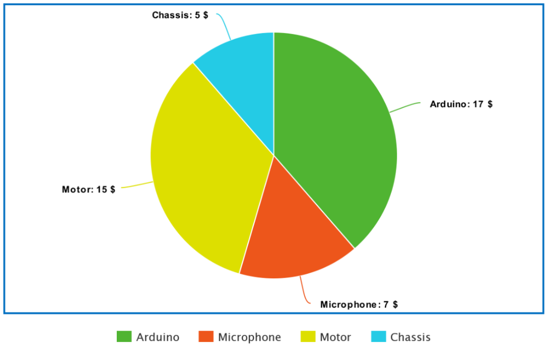
Figure 16: Buget Breakdown
11. Project Management Summary
- Tasks Completed
- prototyping
- audio processing
- activation mechanisims
- motor testing
- enclosure modification
- aesthetically pleasing design
- production model
- saftey stop mechanism
- Kickstarter
- First Look/Pitch Video
- Demo Videos
- Weekly Updates
- Reaching Out To Potential Backers
- Tasks Pending Completion
- Strech Goals
- radar integration
- payload delivery
- Time Allocated Gantt Chart: